The Carron Iron Works was established on the north bank of the River Carron on the lands of Stenhouse in 1759 in order to harness the water for power and transport. The river was already relatively busy with an established harbour at Carronshore complete with infrastructure such as wharfs and ships and, just as importantly, skippers and sailors. The intention was to contract the shipping of Carron Company goods to these third parties as the initial investment had to be focused on the production of cast iron goods.
Between 1759 and 1763 there were innumerable problems in getting building components up the river to the site of the Works and these are clearly noted in Watters’ history of the Company. This transport problem did not end with the completion of the construction work. Cast iron is heavy and water transport was essential in getting the finished articles to market. From a very early date it was apparent to the managers and shareholders of Carron Company that the navigation of the river had to be improved so that larger vessels could carry the products. A two-pronged approach was taken. First, it was agreed to straighten the river to shorten the distance to the Forth and to make it flow faster so that it became self-scouring, enabling larger vessels to use it. Second, Carron Company and its associates were energetic and influential advocates for the construction of a canal across the isthmus from the River Carron to the River Clyde. The intention was, of course, for its eastern terminus to be near Carronshore.
Carron Company had made provision for improved water transport from the very beginning and the agreement reached between Dr Roebuck and Sir Michael Bruce over the site of the new foundry on 13th December 1759 contained a clause:
“for making a Canal and water-course and lead through and over any part of his lands of Stenhouse both to and from the said Forges and Furnaces with full power, liberty and priviledge of Navigating Sloops Boats and Lighters up and down the River Carron as well as in the Canal or Water course before mentioned.”
(Campbell, p.32).
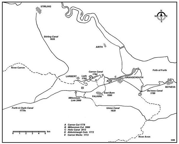
Despite its best endeavours to persuade the backers of the Forth and Clyde Canal that it should end near Carronshore, there were compelling reasons for taking it further down the river. At the last moment, on 11 December 1767, Carron Company agreed to withdraw its opposition to the requisite Parliamentary Bill if the proprietors of the Forth and Clyde Canal permitted a single link with their canal to the Carron Works. After further blustering, Gascoigne, the managing director of Carron Company, got an agreement in February 1768 from Sir Alexander Gilmour and Mr Dundas of Castlecary in the lobby of the House of Commons for two cuts – to Stenhouse dam and to Carronshore according to a plan by Alexander Shepherd of Bo’ness – in order not to oppose their Bill (D on the above map). At the Bill stage Carron Company was assured that its cut had merely been overlooked, and that the clause allowing landowners to make side cuts would be sufficient for their purposes. Gascoigne noted that this clause did not allow for lockage water and would be insufficient. It was pointed out that any vessel using the east end of the canal would need a lockful of water whether they went through the canal or the proposed cut. However, after royal assent for the Forth and Clyde Canal was granted on 8 March 1768 the engineers for the Forth and Clyde Canal refused to ratify the agreement. Furthermore, the Forth and Clyde Canal Co said they were unable to apply any money raised for the Great Canal on side cuts by virtue of the Bill. After considerable effort, including legal action, the Carron Company realised that the proposed link would not happen in the form that it had intended and it made a “temporary cut” at Dalderse instead in 1771 (A on the map).
In 1771 the great cannon boring mill was erected at Carron using the designs of the celebrated engineer John Smeaton. On 22 November that year a sasine was made in favour of Francis Garbett and Charles Gascoigne for the
“milns of Stenhouse shilling hill belonging thereto kilns milners houses & pertinents with the whole sucken multures knaveship & c with the weir or damhead with the miln lead for bringing the said water to the milns and the Canal for carrying off the water from the same with power to widen the said canal betwixt the tails of the wheels of the said milns and river Carron to the Breadth of thirty six feet and to deepen the same if necessary …”.
It seems to have been Smeaton who suggested using the tail-race of the boring mill in combination with the river for small barges. Two ‘lighters’ with a maximum of 8 tons burden were operated by the lightermen James Millar and William Malies. The lighters were tracked, i.e. towed, from the banks by up to six boys and men depending upon the strength and direction of the wind. However, the vast majority of goods went to Carronshore by land, probably along the waggonway using the wagons that had brought coal to the works from Kinnaird. A loading basin was constructed at the east end of an internal work’s canal next to the boring mill. Here goods were transferred on to the lighter lying at a lower level in the mill race and incoming materials had to be carried up the bank.
In March 1779 Gascoigne turned his attention to making a “Navigable Cut” from the harbour at Carronshore to the Works. Negotiations seem to have been opened with Thomas Dundas of Carronhall to lease land next to the river, but to no avail. Dundas even opposed the long-held right to use the river embankments for tracking. Similar dealings with Sir Michael Bruce of Stenhouse for land on the north side of the river in his ownership were more successful, though it was 1782 before an excambion of land took place between Bruce and Gascoigne for part of Mill Quarter. In October 1782 Gascoigne was therefore able to propose to the other partners that the small canal be constructed between the works and the river near to Chapel Burn which formed the boundary between Stenhouse and Carronhall. It would continue the use of the existing mill lade, which was to be enlarged, and extend it eastwards to a single lock where it entered the river. Much of the eastern end of the new canal ran along the course from which the river had been diverted just a few years earlier. Once again John Smeaton was the consulting engineer.
Between the end of the new canal and Carronshore the river was tidal and this restricted the hours during which it could be navigated. Despite Smeaton having suggested that a lock be built between the canal and the river it is therefore doubtful that this was done at the time. A map of 1797 does not indicate the presence of a lock chamber (RHP 242), nor does Grassom on his map of 1817, even though it depicts the locks on the Forth and Clyde Canal. This seems to be confirmed by a court case in 1802 between the Carron Company and John Ogilvie of Carron House 1802 in which it is mentioned that from the Works there was “a short Cut or Canal, filled by every Tide.” Another reason for omitting the lock may have been the problem of obtaining reasonable foundations on the infilled river course. In August 1783 it was announced that “The Canal from Carron Works is now finished; the Carron Shipping Company is now bringing their goods from Carron Works in lighters to their new wharf at Sealock.” (Caledonian Mercury 20 August 1783). It coincided with the removal of two loops of the river at Grangemouth by Lawrence Dundas.
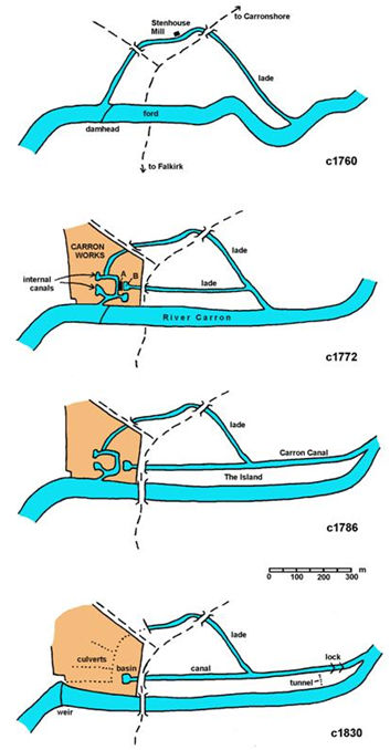
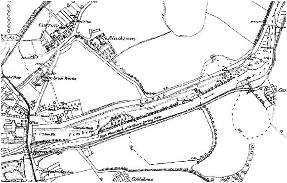
Illus 3: Map illustrating the development of the canal and water system east of Carron Works (after Watters 2010).
The basin at the west end of the canal lay inside the perimeter wall of the Works. It was essentially a swelling of the channel which must have been lined with stone from the beginning to avoid damage from the wash of the boring mill and to provide a firm footing for the loading operations. The long sliver of land between the canal and the river became known locally as “The Island” and was used by Carron Company for storing and sawing timber.
The following year two new lighters of 40 tons burden were acquired by Joseph Stainton, the Warehouse Keeper at Carron, for use on the new canal. He was to become the Company’s next manager. In 1789 the sum of £244.3.4 appears in the accounts for the “Boring Mill Bridge” which must have taken the main road from Falkirk to Airth or Carronshore over the canal. The large cost was presumably because it had to be high enough to allow the barges to pass beneath it (at a later date the upper parts of its stone abutments were removed and a low brick arch inserted over them which still carries the present road). The lease on the waggonways to Carronshore had run out and the bulk of the freight was now taken on the canal and the river. The increase in the size of the lighters meant that they could proceed direct to Grangemouth where the Carron Company established a new wharf. The number of men tracking them increased to between six and twenty.
The next three decades were ones of unprecedented growth for Carron Company as wars in Europe increased its profitability due to the sale of munitions. The return to relative peace actually saw the volume of material leaving Carron increase when the high value weapons destined for a few purchasers were replaced by domestic goods for a wider market. The earlier profits were invested in improving the transport network and in 1824 work started on the construction of an entrance lock from the river to the Carron Canal which would allow the canal to be used for longer periods in the day. This was made possible by the construction of a new weir on the river at the west end of the Works to replace the failing Stenhouse damhead, feeding more water into the canal from the west. A tunnel from the canal to the river 50m west of the lock chamber still enabled tidal water to top up the water level.
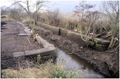
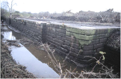
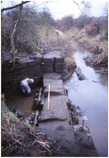
Illus 4: The Lock Chamber looking west. 1994.
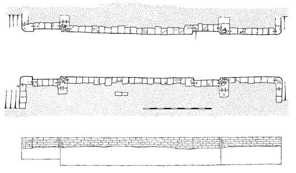
The author was provided with an opportunity to record the lock chamber and sluice in November 1994 in advance of a housing development. Initially only the overgrown ditch-like track of the main navigable cut could be observed but upon the removal and thinning of the dense vegetational cover it was possible to examine the masonry structures. The two parallel side walls of the lock chamber were 38m long and over 3m tall (the bottom had silted up) forming a channel 6.3m wide.
They curved tightly outward at each end to form perpendicular wing walls. The stonework consisted of large, squared blocks with droved faces and rounded margins laid in regular courses and was very well executed. The neatly curved recesses for the pivot posts for the two sets of lock gates occurred at 9.0m from the east end and 5.8m from the west, making then 23m apart and indicating the length of vessel that the system was capable of taking. Each post recess was at the end of a 3.8m long section of the retaining wall inset by 0.4m, designed to take the leaf of the gate so that it would be flush with the side of the chamber when open. The heavy iron straps with radiating arms which once held the collar for the pivot posts had been set into the upper stone block using lead plugs. Each of these stone blocks was then attached to neighbouring blocks by further straps to anchor it in place as there would have been a huge strain on the top of the gates. The corner copestones and those at the other end of the gate recesses were also tied into adjacent blocks. The latter had small iron rings set into the centre of their tops and associated wear marks on the chamber edge from the use of ropes.
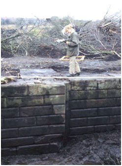
Illus 5: Recess for the Lock Gates.
Adjacent to the post recesses on the north side of the walling, large Roman numerals (0.15m tall) had been neatly carved to indicate the depth of water. That outside the gates on the river side went up to XII, and that inside the chamber to IX, showing that there was a difference in basal levels of 3ft. While this appears to be almost negligible, the lock’s main function was evidently to keep the water in the canal when the tide receded and to allow passage between it and the river at medium states. Retaining the water made loading and unloading much easier.
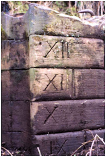
Illus 6: The Eastern Set of Roman Numerals.
The mason who inscribed the lettering was evidently unfamiliar with Roman numerals as he accidentally carved “XII” on the stone above the “X” and so the terminal “I” had to be infilled with white lead putty.
The large cope stone on the south-east corner of the lock chamber had an inscription, much worn, on its upper surface commemorating the construction work. It read: “BUILT/ 1824/ JOSEPH DAWSON MANAGER/ A COPLAND MASON/ – DONALDSON WRIGHT/ A NEILSON WATER”
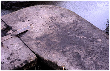
Illus 7: Building Inscriptions.
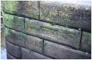
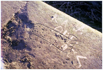
Illus 8: Scroll with the Date of Opening.
The date must be that of the initiation of the scheme as a small inset panel on the west side of the south wing wall contains the date “1826”. This is cut into the second course from the top. What appears to be yet a third building inscription was found on one of the cope stones on the north side of the chamber. Inside a well-formed scroll 0.45m long were two lines of text. Unfortunately the first line of lettering was illegible, but the second line was clear – “4 3 26,” and presumably refers to the official date of the opening.
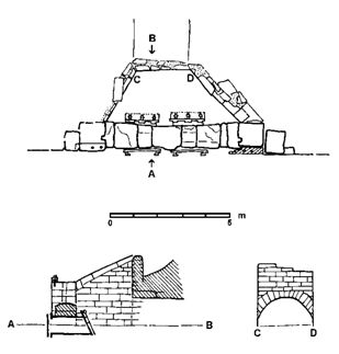
Illus 10: Plan, Elevation and Section of the Sluice/Overflow structure.
Water levels inside the canal were controlled by an overflow weir and sluice linked to the river by a tunnel. The tunnel was 30m long, 2.3m wide and c1.5m high, with stone sides and a brick arch. Its northern end was set back 3.5m from the edge of the canal allowing for a chamfered forecourt at the front of which was the weir. Two courses of large stones were placed above two cast iron conduits set in a wall. The upper course had a rounded top and a thick wooden plank on its north side provided some protection from the barges. Grooves in the walls to either end of the weir allowed planks to be inserted to change the water levels.
The conduits had iron framing on their front (northern) sides to take wooden paddles which would have been operated by steel screws. The conduits were sealed at the back by cast iron clap drain covers.
the Sluice looking west along the Canal 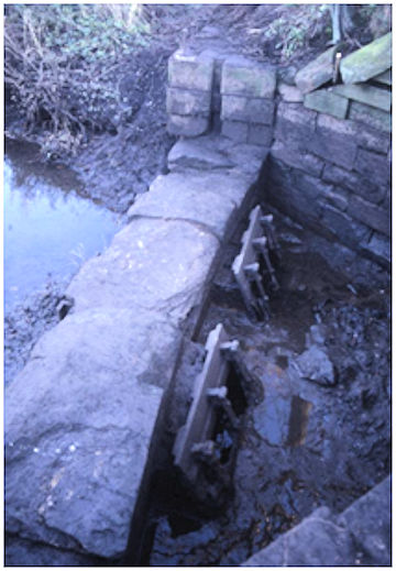
the back of the Overflow with the Clap Valves.
The tunnel was constructed at the point where the old river course used to cross that of the canal, which presumably made digging easier.
The north bank of the canal between the river and a lane to Blacktown House soon became a public right of way – replacing the one that existed on the north bank of the river before it was straightened. The Island to the south belonged to Carron Company and large stone gate piers opposite the foundry office held a sliding gate debarring access to the public. Despite this, it was frequently used as a short cut for those heading to Carronshore. The canal could be crossed on the lock gates. This led to fatal consequences during the long winter nights. In December 1851, for example, a young female servant called Agnes Harley was returning to Carronshore from Carron after visiting her mother when she slipped and her body was found in the canal lock two days later (Falkirk Herald 25 December 1851, 3). Just two years earlier a man named Gibson, when under the influence of drink, had fallen into the Carron Company’s canal and drowned. It was noted that several lives had already been lost within the previous few years at the same place. (Falkirk Herald 11 October 1849).
Writing in 1845 Rev John Bonar noted that the canal was in use: “A cut from the centre of the works connects them with the Carron River. The goods are stowed in lighters, which drop down to Grangemouth with the tide, where they are shipped in smacks for the London market.”
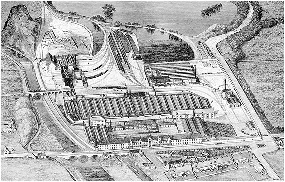
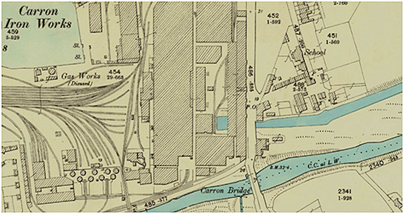
The canal seems to have been retained during the great reconstruction and reorganisation of the Works that was undertaken in the 1880s. The “bird’s-eye view” of the new Works produced to celebrate the achievement shows the canal in the foreground with a steam propelled vessel on it. A large arch takes it under the public road and the edge of the basin can just be made out in the courtyard where a steam train moves away from it.
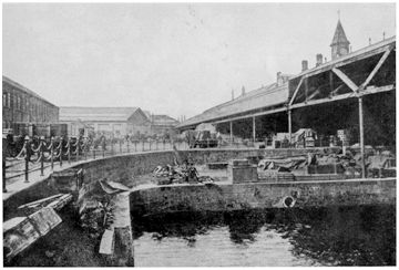
Illus 14: The Canal Basin looking north, c1900.
A photograph of the basin looking north, taken just a few years later, shows the clock tower in the background. The ground level around the basin was raised for the courtyard and the railway tracks introducing another terrace wall round the basin.
However, this was a temporary reprieve for the canal basin. By 1915 it had been filled in and built over. The disused canal was simply abandoned and its banks were soon colonised by trees. The channel continued to be used for discharging water from the Works.
The water was now used as a coolant there and the warm water provided good fishing and swimming for local children – despite the odd piece of floating sewage! With the closure of the Works in the early 1980s even this usage ceased and the vegetation encroached into the channel.
In the late 1990s the Island was developed for self-build dwelling by New Beaumont Homes. The channel was filled in and the top of the lock chamber bulldozed. The latter is now occupied by a nursing home.
SMR 1064 Carron Canal NS 8820 8244 – NS 8898 8280
BIBLIOGRAPHY
| Bailey, G.B. | 1992 | ‘Along and Across the River Carron: a history of communications on the lower reaches of the River Carron,’ Calatria 2, 49-85. |
| Bonar, J | 1845 | Parish of Larbert – New Statistical Account of Scotland |
| Campbell, R.H. | 1961 | Carron Company |
| RHP | Register House Plan. | |
| Watters, B. | 2010 | Carron: Where Iron Runs like Water |
G B Bailey (2021)
